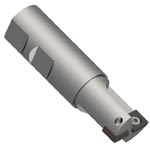
CEM End Mills CEM Series End Mills

Geometry Specifications:
Axial:
0°   Radial: 0°   Shoulder: 90°


CEM Series End Mills free cutting positive geometry accommodates a variety of workpiece materials. Design allows ramping, plunge to depth of chip clearance and peripheral cuts. Engineered for rigidity during plunging or channel cuts. Simple screw insert mounting provides quick accurate indexing. Small shank diameters make CEM ideal for use on all light duty machine tools.


 CEM Series - Dimensional Specifications
Product Number D S L A DOC Insert Teeth
0.5CEMRW2 .500 .500 2.78 90° .200 LEEB-32__ 1
0.62CEMRW2.5 .625 .625 3.00 90° .200 LDEB-32__ 1
0.75CEMRW3 .750 .750 3.25 90° .200 SDEB-32__ 1
0.88CEMRW3.5 .875 .875 3.25 90° .200 SPEB-321 2-(1) Effec.
1.0CEMRW4 1.000 1.000 4.25 90° .200 SPEB-321 2-(1) Effec.

Milling Cutter Nomenclature

 Parts
Insert I.C. & Thickness Insert Number Insert Number Torx Screw Lock Screw Wrench
 
.375 x .125 LDEB-32__ SDEB-32__ 3605-0001-0006
1557-TX10
.375 x .125   SPEB-32__
.375 x .125 LEEB-32__  
Use Checkbox Selections for Multi-Select feature to work


Insert Nomenclature

Starting Machining Parameters
Material SFPM FPT Primary Secondary
Gray Cast Iron, Class 30 200-500 .002-.006 __EB GR LT-45 __EB GR LTC-10
Ductile Iron 350-700 .002-.006 __EB GR LT-40 __EB GR LTC-14
Medium Alloy Steel 300-700 .002-.006 __EB GR LT-40 __EB GR LTC-14
Tool Steel, P20 300-700 .002-.006 __EB GR LT-40 __EB GR LTC-14
Soft Alloy Steel 400-800 .002-.006 __EB GR LT-40 __EB GR LTC-14